- Overview
- Configuration
- NTP4 Plug-In
- Hardware
- RFC 868
- RFC 2030
-
RFC 1305
- RFC 1305
- 1. Introduction
- 1.1 Related Technology
- 2. System Architecture
- 2.1 Implementation Model
- 2.2 Network Configurations
- 3. Network Time Protocol
- 3.1 Data Formats
- 3.2 State Variables and Parameters
- 3.2.1 Common Variables
- 3.2.2 System Variables
- 3.2.3 Peer Variables
- 3.2.4 Packet Variables
- 3.2.5 Clock-Filter Variables
- 3.2.6 Authentication Variables
- 3.2.7 Parameters
- 3.3 Modes of Operation
- 3.4 Event Processing
- 3.4.1 Notation Conventions
- 3.4.2 Transmit Procedure
- 3.4.3 Receive Procedure
- 3.4.4 Packet Procedure
- 3.4.5 Clock-Update Procedure
- 3.4.6 Primary-Clock Procedure
- 3.4.7 Initialization Procedures
- 3.4.7.1 Initialization Procedure
- 3.4.7.2 Initialization-Instantiation Procedure
- 3.4.7.3 Receive-Instantiation Procedure
- 3.4.7.4 Primary Clock-Instantiation Procedure
- 3.4.8 Clear Procedure
- 3.4.9 Poll-Update Procedure
- 3.5 Synchronization Distance Procedure
- 3.6 Access Control Issues
- 4. Filtering and Selection Algorithms
- 4.1 Clock-Filter Procedure
- 4.2 Clock-Selection Procedure
- 4.2.1 Intersection Algorithm
- 4.2.2. Clustering Algorithm
- 5. Local Clocks
- 5.1 Fuzzball Implementation
- 5.2 Gradual Phase Adjustments
- 5.3 Step Phase Adjustments
- 5.4 Implementation Issues
- 6. Acknowledgments
- 7. References
- Appendix A
- Appendix B
- Appendix C
- Appendix D
- Appendix E
- Appendix F
- Appendix G
- Appendix H
- Appendix I
- Time Tools
- NTP Auditor
- About
| Previous Top Next |
Windows Time Server
Appendix BNTP Control Messages
In a comprehensive network-management environment, facilities are presumed available to perform routine NTP control and monitoring functions, such as setting the leap-indicator bits at the primary servers, adjusting the various system parameters and monitoring regular operations. Ordinarily, these functions can be implemented using a network-management protocol such as SNMP and suitable extensions to the MIB database. However, in those cases where such facilities are not available, these functions can be implemented using special NTP control messages described herein. These messages are intended for use only in systems where no other management facilities are available or appropriate, such as in dedicated-function bus peripherals. Support for these messages is not required in order to conform to this specification.
The NTP Control Message has the value 6 specified in the mode field of the first octet of the NTP header and is formatted as shown below. The format of the data field is specific to each command or response; however, in most cases the format is designed to be constructed and viewed by humans and so is coded in free-form ASCII. This facilitates the specification and implementation of simple management tools in the absence of fully evolved network-management facilities. As in ordinary NTP messages, the authenticator field follows the data field. If the authenticator is used the data field is zero-padded to a 32-bit boundary, but the padding bits are not considered part of the data field and are not included in the field count.
IP hosts are not required to reassemble datagrams larger than 576 octets; however, some commands or responses may involve more data than will fit into a single datagram. Accordingly, a simple reassembly feature is included in which each octet of the message data is numbered starting with zero. As each fragment is transmitted the number of its first octet is inserted in the offset field and the number of octets is inserted in the count field. The more-data (M) bit is set in all fragments except the last.
Most control functions involve sending a command and receiving a response, perhaps involving several fragments. The sender chooses a distinct, nonzero sequence number and sets the status field and R and E bits to zero. The responder interprets the opcode and additional information in the data field, updates the status field, sets the R bit
to one and returns the three 32-bit words of the header along with additional information in the data field. In case of invalid message format or contents the responder inserts a code in the status field, sets the R and E bits to one and, optionally, inserts a diagnostic message in the data field.
Some commands read or write system variables and peer variables for an association identified in the command. Others read or write variables associated with a radio clock or other device directly connected to a source of primary synchronization information. To identify which type of variable and association a 16-bit association identifier is used. System variables are indicated by the identifier zero. As each association is mobilized a unique, nonzero identifier is created for it. These identifiers are used in a cyclic fashion, so that the chance of using an old identifier which matches a newly created association is remote. A management entity can request a list of current identifiers and subsequently use them to read and write variables for each association. An attempt to use an expired identifier results in an exception response, following which the list can be requested again.
Some exception events, such as when a peer becomes reachable or unreachable, occur spontaneously and are not necessarily associated with a command. An implementation may elect to save the event information for later retrieval or to send an asynchronous response (called a trap) or both. In case of a trap the IP address and port number is determined by a previous command and the sequence field is set as described below. Current status and summary information for the latest exception event is returned in all normal responses. Bits in the status field indicate whether an exception has occurred since the last response and whether more than one exception has occurred.
Commands need not necessarily be sent by an NTP peer, so ordinary access-control procedures may not apply; however, the optional mask/match mechanism suggested elsewhere in this document provides the capability to control access by mode number, so this could be used to limit access for control messages (mode 6) to selected address ranges.
NTP Control Message Format
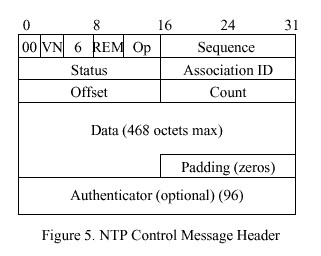
The format of the NTP Control Message header, which immediately follows the UDP header, is shown in Figure 5. Following is a description of its fields. Bit positions marked as zero are reserved and should always be transmitted as zero.
Version Number (VN): This is a three-bit integer indicating the NTP version number, currently three (3).
Mode: This is a three-bit integer indicating the mode. It must have the value 6, indicating an NTP control message.
Response Bit (R): Set to zero for commands, one for responses.
Error Bit (E): Set to zero for normal response, one for error response.
More Bit (M): Set to zero for last fragment, one for all others.
Operation Code (Op): This is a five-bit integer specifying the command function. Values currently defined include the following:
0 |
reserved |
1 |
read status command/response |
2 |
read variables command/response |
3 |
write variables command/response |
4 |
read clock variables command/response |
5 |
write clock variables command/response |
6 |
set trap address/port command/response |
7 |
trap response |
8-31 |
reserved |
Sequence: This is a 16-bit integer indicating the sequence number of the command or response.
Status: This is a 16-bit code indicating the current status of the system, peer or clock, with values coded as described in following sections.
Association ID: This is a 16-bit integer identifying a valid association.
Offset: This is a 16-bit integer indicating the offset, in octets, of the first octet in the data area.
Count: This is a 16-bit integer indicating the length of the data field, in octets.
Data: This contains the message data for the command or response. The maximum number of data octets is 468.
Authenticator (optional): When the NTP authentication mechanism is implemented, this contains the authenticator information defined in Appendix C.
Status Words
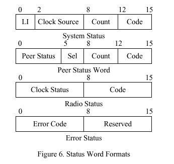
Status words indicate the present status of the system, associations and clock. They are designed to be interpreted by network-monitoring programs and are in one of four 16-bit formats shown in Figure 6 and described in this section. System and peer status words are associated with responses for all commands except the read clock variables, write clock variables and set trap address/port commands. The association identifier zero specifies the system status word, while a nonzero identifier specifies a particular peer association. The status word returned in response to read clock variables and write clock variables commands indicates the state of the clock hardware and decoding software. A special error status word is used to report malformed command fields or invalid values.
System Status Word
The system status word appears in the status field of the response to a read status or read variables command with a zero association identifier. The format of the system status word is as follows:
Leap Indicator (LI): This is a two-bit code warning of an impending leap second to be inserted/deleted in the last minute of the current day, with bit 0 and bit 1, respectively, coded as follows:
00 |
no warning |
01 |
last minute has 61 seconds |
10 |
last minute has 59 seconds) |
11 |
alarm condition (clock not synchronized) |
Clock Source: This is a six-bit integer indicating the current synchronization source, with values coded as follows:
0 |
unspecified or unknown |
1 |
Calibrated atomic clock (e.g.,, HP 5061) |
2 |
VLF (band 4) or LF (band 5) radio (e.g.,, OMEGA,, WWVB) |
3 |
HF (band 7) radio (e.g.,, CHU,, MSF,, WWV/H) |
4 |
UHF (band 9) satellite (e.g.,, GOES,, GPS) |
5 |
local net (e.g.,, DCN,, TSP,, DTS) |
6 |
UDP/NTP |
7 |
UDP/TIME |
8 |
eyeball-and-wristwatch |
9 |
telephone modem (e.g.,, NIST) |
10-63 |
reserved |
System Event Counter: This is a four-bit integer indicating the number of system exception events occurring since the last time the system status word was returned in a response or included in a trap message. The counter is cleared when returned in the status field of a response and freezes when it reaches the value 15.
System Event Code: This is a four-bit integer identifying the latest system exception event, with new values overwriting previous values, and coded as follows:
0 |
unspecified |
1 |
system restart |
2 |
system or hardware fault |
3 |
system new status word (leap bits or synchronization change) |
4 |
system new synchronization source or stratum (sys.peer or sys.stratum change) |
5 |
system clock reset (offset correction exceeds CLOCK.MAX) |
6 |
system invalid time or date (see NTP specification) |
7 |
system clock exception (see system clock status word) |
8-15 |
reserved |
Peer Status Word
A peer status word is returned in the status field of a response to a read status, read variables or write variables command and appears also in the list of association identifiers and status words returned by a read status command with a zero association identifier. The format of a peer status word is as follows:
Peer Status: This is a five-bit code indicating the status of the peer determined by the packet procedure, with bits assigned as follows:
0 |
configured (peer.config) |
1 |
authentication enabled (peer.authenable) |
2 |
authentication okay (peer.authentic) |
3 |
reachability okay (peer.reach <F128M>Ö<F255D> 0) |
4 |
reserved |
Peer Selection (Sel): This is a three-bit integer indicating the status of the peer determined by the clock-selection procedure, with values coded as follows:
0 |
rejected |
1 |
passed sanity checks (tests 1 through 8 in Section 3.4.3) |
2 |
passed correctness checks (intersection algorithm in Section 4.2.1) |
3 |
passed candidate checks (if limit check implemented) |
4 |
passed outlyer checks (clustering algorithm in Section 4.2.2) |
5 |
current synchronization source; max distance exceeded (if limit check implemented) |
6 |
current synchronization source; max distance okay |
7 |
reserved |
Peer Event Counter: This is a four-bit integer indicating the number of peer exception events that occurred since the last time the peer status word was returned in a response or included in a trap message. The counter is cleared when returned in the status field of a response and freezes when it reaches the value 15.
Peer Event Code: This is a four-bit integer identifying the latest peer exception event, with new values overwriting previous values, and coded as follows:
0 |
unspecified |
1 |
peer IP error |
2 |
peer authentication failure (peer.authentic bit was one now zero) |
3 |
peer unreachable (peer.reach was nonzero now zero) |
4 |
peer reachable (peer.reach was zero now nonzero) |
5 |
peer clock exception (see peer clock status word) |
6-15 |
reserved |
Clock Status Word
There are two ways a reference clock can be attached to a NTP service host, as an dedicated device managed by the operating system and as a synthetic peer managed by NTP. As in the read status command, the association identifier is used to identify which one, zero for the system clock and nonzero for a peer clock. Only one system clock is
supported by the protocol, although many peer clocks can be supported. A system or peer clock status word appears in the status field of the response to a read clock variables or write clock variables command. This word can be considered an extension of the system status word or the peer status word as appropriate. The format of the clock status word is as follows:
Clock Status: This is an eight-bit integer indicating the current clock status, with values coded as follows:
0 |
clock operating within nominals |
1 |
reply timeout |
2 |
bad reply format |
3 |
hardware or software fault |
4 |
propagation failure |
5 |
bad date format or value |
6 |
bad time format or value |
7-255 |
reserved |
Clock Event Code: This is an eight-bit integer identifying the latest clock exception event, with new values overwriting previous values. When a change to any nonzero value occurs in the radio status field, the radio status field is copied to the clock event code field and a system or peer clock exception event is declared as appropriate.
Error Status Word
An error status word is returned in the status field of an error response as the result of invalid message format or contents. Its presence is indicated when the E (error) bit is set along with the response (R) bit in the response. It consists of an eight-bit integer coded as follows:
0 |
unspecified |
1 |
authentication failure |
2 |
invalid message length or format |
3 |
invalid opcode |
4 |
unknown association identifier |
5 |
unknown variable name |
6 |
invalid variable value |
7 |
administratively prohibited |
8-255 |
reserved |
Commands
Commands consist of the header and optional data field shown in Figure 6. When present, the data field contains a list of identifiers or assignments in the form
<<identifier>>[=<<value>>],<<identifier>>[=<<value>>],...
where <<identifier>> is the ASCII name of a system or peer variable specified in Table 2 or Table 3 and <<value>> is expressed as a decimal, hexadecimal or string constant in the syntax of the C programming language. Where no ambiguity exists, the sys or peer prefixes shown in Table 2 or Table 4 can be suppressed. White space (ASCII nonprinting format effectors) can be added to improve readability for simple monitoring programs that do not reformat the data field. Internet addresses are represented as four octets in the form [n.n.n.n], where n is in decimal notation and the brackets are optional. Timestamps, including reference, originate, receive and transmit values, as well as the logical clock, are represented in units of seconds and fractions, preferably in hexadecimal notation, while delay, offset, dispersion and distance values are represented in units of milliseconds and fractions, preferably in decimal notation. All other values are represented as-is, preferably in decimal notation.
Implementations may define variables other than those listed in Table 2 or Table 3. Called extramural variables, these are distinguished by the inclusion of some character type other than alphanumeric or . in the name. For those commands that return a list of assignments in the response data field, if the command data field is empty, it is expected that all available variables defined in Table 3 or Table 4 of the NTP specification will be included in the response. For the read commands, if the command data field is nonempty, an implementation may choose to process this field to individually select which variables are to be returned.
Commands are interpreted as follows:
Read Status (1): The command data field is empty or contains a list of identifiers separated by commas. The command operates in two ways depending on the value of the association identifier. If this identifier is nonzero, the response includes the peer identifier and status word. Optionally, the response data field may contain other information, such as described in the Read Variables command. If the association identifier is zero, the response includes the system identifier (0) and status word, while the data field contains a list of binary-coded pairs
<<association identifier>> <<status word>>,
one for each currently defined association. Read Variables (2): The command data field is empty or contains a list
of identifiers separated by commas. If the association identifier is nonzero, the response includes the requested peer identifier and status word, while the data field contains a list of peer variables and values as described above. If the association identifier is zero, the data field contains a list of system variables and values. If a peer has been
selected as the synchronization source, the response includes the peer identifier and status word; otherwise, the response includes the system identifier (0) and status word.
Write Variables (3): The command data field contains a list of assignments as described above. The variables are updated as indicated. The response is as described for the Read Variables command.
Read Clock Variables (4): The command data field is empty or contains a list of identifiers separated by commas. The association identifier selects the system clock variables or peer clock variables in the same way as in the Read Variables command. The response includes the requested clock identifier and status word and the data field contains a list of clock variables and values, including the last timecode message received from the clock.
Write Clock Variables (5): The command data field contains a list of assignments as described above. The clock variables are updated as indicated. The response is as described for the Read Clock Variables command.
Set Trap Address/Port (6): The command association identifier, status and data fields are ignored. The address and port number for subsequent trap messages are taken from the source address and port of the control message itself. The initial trap counter for trap response messages is taken from the sequence field of the command. The response association identifier, status and data fields are not significant. Implementations should include sanity timeouts which prevent trap transmissions if the monitoring program does not renew this information after a lengthy interval.
Trap Response (7): This message is sent when a system, peer or clock exception event occurs. The opcode field is 7 and the R bit is set. The trap counter is incremented by one for each trap sent and the sequence field set to that value. The trap message is sent using the IP address and port fields established by the set trap address/port command. If a
system trap the association identifier field is set to zero and the status field contains the system status word. If a peer trap the association identifier field is set to that peer and the status field contains the peer status word. Optional ASCII-coded information can be included in the data field.